링버퍼 구현 verilog
FIFO(First In First Out) Buffer in Verilog
First Out) buffer is an elastic storage usually used between two subsystems. As the name indicates the memory that is first written into the FIFO is the first to be read or processed. A FIFO has two control signals i.e. write and read. When write is enabled data is written into the buffer and when read is enabled data is "removed" from the buffer to make room for more data. This concept of write and read (remove) can be best understood from the conceptual diagram of a FIFO below:
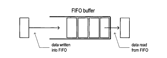
As can be seen, once the data is read, it can be considered as removed and thus allowing more data to be written into the buffer.
Implementation of FIFO in Verilog
To implement FIFO in verilog imagine the memory components to be arranged in a circular queue fashion with two pointers; write and read. The write pointer points to the start of the circle whereas the read pointer points to the end of the circle. Both these pointers increment themselves by one after each read or write operation.
This buffer will also consist of two flags; empty and full. These will help in indicating when the FIFO is full (cannot be written to) or empty (cannot be read from). This circular implementation can be seen from the following figure:

The size of the FIFO buffer greatly depends on the number of address bits. As the number of words in fifo = 2^(number of address bits). The FIFO I will be coding here will consist of 16 memory elements ( 4 bits in each memory element and 3 address bits). This can be easily changed by changing the parameters in the code, by doing so you can create a buffer of any size. The parameters can be changed from the following line:
module fifo # (parameter abits = 4, dbits = 3)
At reset the empty flag is set to high whereas the full flag is set to low to allow new data to be written. The positions of the read and write pointers are also initialized to 0. The verilog code is shown below. It has been commented in detail so I hope each step is clear.
module fifo # (parameter abits = 4, dbits = 3)( input clock, input reset, input wr, input rd, input [dbits-1:0] din, output empty, output full, output [dbits-1:0] dout ); wire db_wr, db_rd; reg dffw1, dffw2, dffr1, dffr2; reg [dbits-1:0] out; always @ (posedge clock) dffw1 <= wr; always @ (posedge clock) dffw2 <= dffw1; assign db_wr = ~dffw1 & dffw2; //monostable multivibrator to detect only one pulse of the button always @ (posedge clock) dffr1 <= rd; always @ (posedge clock) dffr2 <= dffr1; assign db_rd = ~dffr1 & dffr2; //monostable multivibrator to detect only one pulse of the button reg [dbits-1:0] regarray[2**abits-1:0]; //number of words in fifo = 2^(number of address bits) reg [abits-1:0] wr_reg, wr_next, wr_succ; //points to the register that needs to be written to reg [abits-1:0] rd_reg, rd_next, rd_succ; //points to the register that needs to be read from reg full_reg, empty_reg, full_next, empty_next; assign wr_en = db_wr & ~full; //only write if write signal is high and fifo is not full //always block for write operation always @ (posedge clock) begin if(wr_en) regarray[wr_reg] <= din; //at wr_reg location of regarray store what is given at din end //always block for read operation always @ (posedge clock) begin if(db_rd) out <= regarray[rd_reg]; end always @ (posedge clock or posedge reset) begin if (reset) begin wr_reg <= 0; rd_reg <= 0; full_reg <= 1'b0; empty_reg <= 1'b1; end else begin wr_reg <= wr_next; //created the next registers to avoid the error of mixing blocking and non blocking assignment to the same signal rd_reg <= rd_next; full_reg <= full_next; empty_reg <= empty_next; end end always @(*) begin wr_succ = wr_reg + 1; //assigned to new value as wr_next cannot be tested for in same always block rd_succ = rd_reg + 1; //assigned to new value as rd_next cannot be tested for in same always block wr_next = wr_reg; //defaults state stays the same rd_next = rd_reg; //defaults state stays the same full_next = full_reg; //defaults state stays the same empty_next = empty_reg; //defaults state stays the same case({db_wr,db_rd}) //2'b00: do nothing LOL.. 2'b01: //read begin if(~empty) //if fifo is not empty continue begin rd_next = rd_succ; full_next = 1'b0; if(rd_succ == wr_reg) //all data has been read empty_next = 1'b1; //its empty again end end 2'b10: //write begin if(~full) //if fifo is not full continue begin wr_next = wr_succ; empty_next = 1'b0; if(wr_succ == (2**abits-1)) //all registers have been written to full_next = 1'b1; //its full now end end 2'b11: //read and write begin wr_next = wr_succ; rd_next = rd_succ; end //no empty or full flag will be checked for or asserted in this state since data is being written to and read from together it can not get full in this state. endcase end assign full = full_reg; assign empty = empty_reg; assign dout = out; endmodule
ref. site : http://simplefpga.blogspot.kr/2012/12/fifofirst-in-first-out-buffer-in-verilog.html
'일 > Knowledge' 카테고리의 다른 글
| Modern Microprocessor architecture - 현대의 Processor 특징 (0) | 2017.06.09 |
|---|---|
| service latency (0) | 2016.11.14 |
| queueing system ( queueing theory ) (0) | 2016.11.14 |
| bit sum (verilog) (0) | 2016.11.11 |
| ready valid protocol 설명. ( verilog ) (0) | 2016.11.09 |